Gia công Cnc của mô hình phun quạt và lõi
|
Đây là nguyên công khó khăn và khó khăn nhất trong quá trình gia công khoang và lõi trong quá trình sản xuất khuôn nhựa, bao gồm quá trình CNC và EDM. Lập trình đường chạy dao CNC là nhiệm vụ quan trọng của toàn bộ quá trình sản xuất, quyết định chất lượng của CNC và độ khó của EDM. This paper discussed the application of Cimatron software in the machining of the cavity and core of fan injection mold, and analyzed its quá trình chạy máy, then focused on explaining the realization of its rough and fine machining. Finally, through the simulation of the toolpath proved the method’s reasonability. |
At present, the machining of mold cavities has become an important field of Cơ khí CNC, especially the machining of cavity mold forming parts is closely related to Cơ khí CNC. In the machining of cavity mold forming parts, it is necessary to go through three processes: product three-dimensional model modeling, product splitting and electrode splitting based on product three-dimensional model, and tool path preparation based on mold cores and electrodes generated by splitting. Unopenable 3D CAD/CAM software. At present, most CAD/CAM software can realize the three functions of modeling, splitting and disassembling electrodes, and programming toolpaths, such as Pro/E, UG, MasterCAM, Cimatron, etc. Among them, Pro/E is more popular for modeling and splitting. For machining, MasterCAM and Cimatron are more popular. This article will take an example of fan mold cavity core machining, and introduce some actual conditions of using Cimatron to process mold forming parts, so as to provide references for mold cavity and core machining.
2 Introduction to machining objects
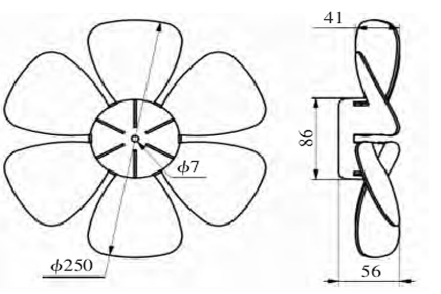
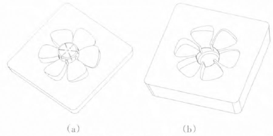
As shown in Figure 1, the plastic part is an electric fan ABS plastic blade with a size range of 250×250×50mm. The modeling is mainly completed in Pro/E by thickening the surface to become a solid body, and then using Pro/Mold in Pro/E The module realizes the parting, and the three-dimensional effect of the cavity and core after parting is shown in Figure 2.
Yêu cầu kỹ thuật:
- ①Material ABS;
- ②The wall thickness of the plastic part is 2mm;
- ③The plastic part must not have pores, cracks and other defects;
- ④The surface of the plastic part must not have burrs (flash);
- ⑤The opening size is subject to the 3D model.
For the mold cavity of the plastic part, it is mainly necessary to machine the curved surface shape of the blade, and to maintain the verticality and accuracy of the inner cavity side wall, so as to ensure the close contact between the cavity and the core, and when forming the plastic part So there will be no flash. In addition, in order to facilitate the installation of the outer wall of the cavity and the core, the thicker cavity is usually processed into a wedge shape, so that the side wall and the bottom surface are not perpendicular, but a steep slope with a certain angle to the vertical, about 1° ~5°, need to pay attention to during machining. The following is a process analysis with the machining of the cavity.
This mold forming part needs to be processed into two sides, front and back. The front side mainly mills the inside of the cavity and the upper end surface. For positioning, the outer side wall must be precision milled. After the front side is processed, the workpiece is turned over, the bottom surface is milled, and then the steep slope of the outer side wall is processed.
The mold cavity is generally pre-hardened steel with a hardness of 38~45HRC, which has a higher hardness. When choosing a tool, you should consider using a tungsten steel knife or a knife with a special coating.
In the core, there are 6 2mm wide rib forming seams, which are relatively deep, and can be processed with a small knife to break the knife, which can be left for EDM machining.
3 Machining technology analysis
For the machining of the mold cavity, a suitable pre-hardened steel blank material must be selected for CNC milling, and a margin of 0.1~0.2mm shall be reserved for grinding and manual grinding by a grinder. For the narrow and deep places in the cavity, it is necessary to select electrical discharge machining and manual polishing after CNC milling. The thread of the threaded hole can be manually tapped after the numerical control drilling pre-hole. In view of the fact that the front and back sides of the cavity and the surrounding sides are mating surfaces, the cavity and the core are processed in both front and back directions. The back side (ie the bottom) must be processed first to complete the milling of the bottom end surface and the surrounding side walls, mainly The final shape of the bottom of the cavity is relatively flat, and it is easy to clamp after machining. After finishing the reverse surface machining, turn the workpiece over for machining, milling the forming part of the cavity, if the outer wall of the cavity has a draft surface, it is necessary to consider using a machining center or a CNC milling machine with an electromagnetic adsorption table.
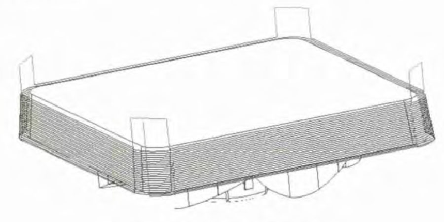
The preparation of this machining toolpath is carried out by the more popular Cimatron software. Before performing specific machining procedures in Cimatron, the cavity entity files in Pro/E must be converted into iges format files, and then input into Cimatron for coordinate setting. It is determined that in the cavity and core machining of the fan mold cavity, a coordinate system is set up on the upper and lower end faces, and the vertical end faces in the Z-axis direction are facing outwards. The Cimatron tool path programming interface is shown in Figure 3 [2 ].
When the mold cavity is processed by CNC milling, it usually includes rough machining, semi-finishing, and finishing. The principle of roughing is to remove the excess metal as efficiently as possible, so it is hoped to choose a large-size tool, but the tool size is too large, which may lead to an increase in the unprocessed volume; the task of semi-finishing is mainly to remove the leftovers from roughing The step; finishing mainly guarantees the size and surface quality of the parts. Taking into account the efficiency and quality, the CNC machining process is arranged as shown in Table 1 [3].
4 Preparation of roughing toolpath
For the cavity and core of the fan mold, square blanks are used, and a lot of volume needs to be removed, especially the core is almost half. The machining is very important.
(1) 2.5-axis cavity milling.
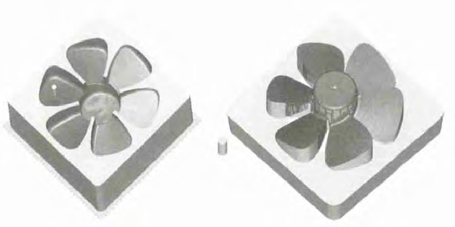
2.5 Axis cavity milling is a commonly used two-dimensional milling command in the Cimatron command, which can be processed within a specific contour range. This command is used for the table surface perpendicular to the Z axis in the cavity. As shown in Figure 4a, it is the rough milling of the outer peripheral platform of the fan core. The milling contour range is the range between the rectangular outer contour and the plum blossom inner contour. The maximum value of the Z axis is 0, and the minimum value is -55mm, from the outside to the inside. For ring cutting machining, the margin is 0.6mm. Check the option to clean the gap between rows. The final result is that the entire tool path is continuous, with almost no empty tools, and few tool lifts. It is an efficient tool path.
(2) 3D circular cutting with volume milling.
For the molding cavity part between the cavity and the core, because the curved surface is relatively complicated, volumetric milling 3D circular cutting is adopted. Volume milling 3D ring cutting is mainly used to achieve the purpose of removing the uneven volume at the bottom. The key is the choice of “machining contour” and “part surface”. Figure 4b is the core volume milling 3D ring cutting tool path. Select all surfaces as the “part surface”, take the margin as 0.6mm, and then use the sketch tool to create a circle with a diameter of 251mm as a contour. The advantage of this is that it can be used as a contour. It makes the tool path less turning, less empty tools, and at the same time, it can also remove some unprocessed areas between the two blades. If the plum-shaped profile is selected, this effect cannot be achieved. Figure 5 shows the 3D circular cutting tool path for volumetric cavity milling. The plum contour is directly selected for the contour, and all the surfaces of the part surface are selected. Since the removal volume is within the plum contour, the tool path is also very coherent and there are fewer empty tools.
5 Preparation of finishing tool path
There are many methods for finishing the fan cavity and core, mainly using the following 3 methods:
(1) Circular cutting of 2.5-axis cavity milling.
The finish milling of the plane is mainly achieved by using the “3D ring cutting” item under 2.5-axis cavity milling. Figure 6 shows the fine milling tool path of the core peripheral platform. While milling the plane, the convex contour of the forming part is also made. For fine milling, considering the slit area, a flat knife with a diameter of ϕ6mm is used, and the margin is 0.15mm.
(2) Surface milling of parts with streamline milling.
It is mainly used for precision milling of smoothly transitioned surfaces, and the generated tool path also transitions smoothly according to the direction of the surface, and the milling range is within the surface. That is, streamline milling is used, and the steep slope of the surrounding side wall is selected for milling, the direction is the circumferential direction, and the margin is 0.15mm.
(3) Finish milling all with curved surface milling.
Surface milling and finishing milling are mainly used for milling complex-shaped surfaces, and the contour range of the machining must be selected. Select all surfaces as “part surfaces” and take the margin as 0.15mm. In the core, you must use the sketch tool to create two circles with a diameter of φ251mm and φ20mm as the machining contour, so that the machining tool path is smoother. In the cavity, you only need to select the plum-shaped contour.
6 Entity verification results
The side wall of the core gives a sloped machining effect, and the side wall of the cavity is a straight wall machining effect. In the specific machining, it is selected according to the needs of the mold design.
7 nhận xét kết luận
The machining of the mold cavity of the fan is of medium difficulty in the machining of the mold cavity, which can reflect all aspects of the mold cavity machining, and has a typical representative significance. In this paper, from the analysis of the CNC machining process of the fan mold cavity machining, the realization of rough and finishing machining and the analysis of its important and difficult points, the CNC milling machining method of the general mold cavity is given. The shape of the mold cavity varies widely. In the CNC machining, the processor should reasonably arrange the machining procedures according to the specific conditions of the machining object, combined with the advantages of the CAM software, in order to compile high-efficiency and high-quality machining toolpaths.

 Cửa hàng PTJ CNC sản xuất các bộ phận có tính chất cơ học tuyệt vời, độ chính xác và độ lặp lại từ kim loại và nhựa. Phay CNC 5 trục có sẵn.